
fe-safe
Accurate strain-based fatigue analysis with direct interfaces to all leading FEA suites
What Can You Do with fe-safe?
Accurate Fatigue Analysis
Advanced multiaxial algorithms are the core of fe-safe. Unique nodal elimination methods ensure no trade-off between speed and accuracy. Users consistently report excellent correlation with test results.
Fast Results
Highly efficient coding plus parallel and distributed processing allow fe-safe to analyse large FE models and report results quickly. Assemblies of different parts, surface finishes and materials can be analysed in a single run.
Easy to Use
fe-safe has many default settings and automatically selects the most appropriate algorithm based on the selected material. Standard analyses can be saved making it ideal for the non-specialist fatigue analyst, but fe-safe is also highly configurable for the advanced user.
What Can You Solve with fe-safe?
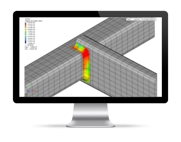
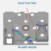
fe-safe uses advanced critical plane multiaxial fatigue with in-built plasticity modelling to post-process results from an elastic FEA. Results can be displayed as contour plots showing crack locations and fatigue lives.
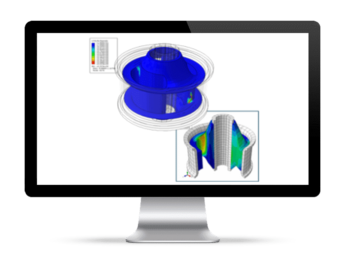
fe-safe uses critical distance methods to check whether cracks will propagate. Allowing cracks to initiate but not propagate to failure may allow higher working stresses and lighter and more efficient designs.

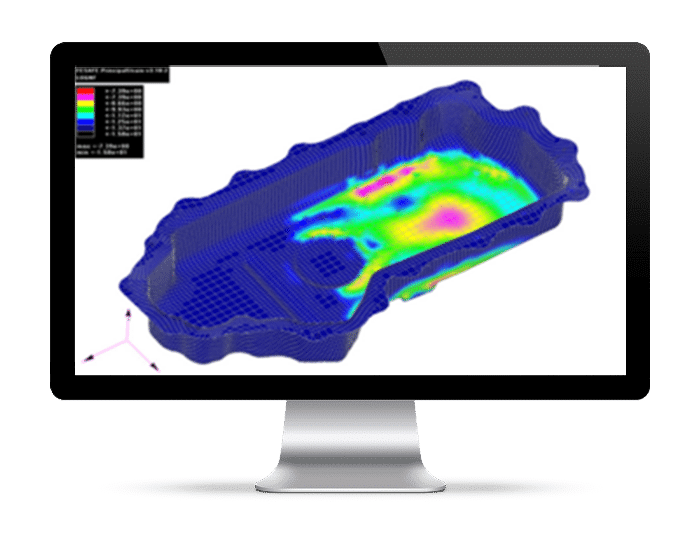
fe-safe calculates the allowable stresses or loads to achieve a specified service life. This is the factor of strength (FOS). fe-safe fully accounts for any changes in plasticity that may be caused by changes in loads or stresses. fe-safe shows how much the design is over-strength or under-strength at each node. Results are displayed as contour plots.
The ‘warranty claim’ calculation combines variability in material strength and variability in loading to estimate the proportion of components uncracked after any period of time in service. This can be used to achieve uniform reliability over different parts of an assembly. Factor of Strength (FOS) and Probability of Survival calculations can be combined with the initial fatigue life calculation in a single run. Together they show the interaction between design stress margins and component reliability.

fe-safe performs a load sensitivity analysis to show the effect of each applied load. This can be used to refine the design and to design and validate an accelerated fatigue test. Once the critical and non-critical loads have been identified, test programs can be optimized and validated by removing unrepresentative tests.

fe-safe can provide detailed results for hot-spot areas or individual elements or nodes, time histories of calculated stresses and strains, fatigue cycle and damage histograms, Haigh and Smith plots and many other graphs to explain why the fatigue life is what it is.
How Can fe-safe Help You Better Understand Your Product Design?
What is the fatigue life of this component?
Use advanced critical plane multiaxial fatigue with in-built plasticity modelling to post-process results from an elastic FEA. Results can be displayed as contour plots showing crack locations and fatigue lives.
Will cracks propagate?
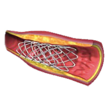
Use critical distance methods to check whether cracks will propagate. Allowing cracks to initiate but not propagate to failure may allow higher working stresses and lighter and more efficient designs.
Where can material be saved? Where must extra material be added?
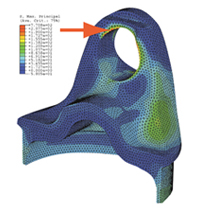
Calculate the allowable stresses or loads to achieve a specified service life. This is the factor of strength (FOS). fe-safe fully accounts for any changes in plasticity that may be caused by changes in loads or stresses. fe-safe shows how much the design is over-strength or under-strength at each node. Results are displayed as contour plots.
How reliable is this design?
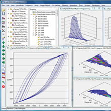
The ‘warranty claim’ calculation combines variability in material strength and variability in loading to estimate the proportion of components uncracked after any period of time in service. This can be used to achieve uniform reliability over different parts of an assembly. Factor of Strength (FOS) and Probability of Survival calculations can be combined with the initial fatigue life calculation in a single run. Together they show the interaction between design stress margins and component reliability.
Which loads are causing fatigue damage?
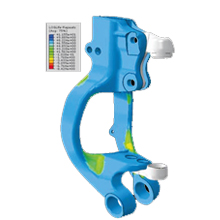
Perform a load sensitivity analysis to show the effect of each applied load. This can be used to refine the design and to design and validate an accelerated fatigue test. Once the critical and non-critical loads have been identified, test programs can be optimized and validated by removing unrepresentative tests.
What is causing fatigue cracking?
Generate detailed results for hot-spot areas or individual elements or nodes, time histories of calculated stresses and strains, fatigue cycle and damage histograms, Haigh and Smith plots and many other graphs to explain why the fatigue life is what it is.
fe-safe: The Fatigue Post-Processor for FEA
- Optimize designs to use less material
- Reduce product recalls and warranty costs
- Optimize and validate design and test programmes
- Improve correlation between test and analysis within a single user interface
- Reduce prototype test times
- Speed up analysis time, thereby reducing man-time hours
- Increase confidence that your product designs pass their test schedules as "right first time"
