Creating a new part in Abaqus/CAE
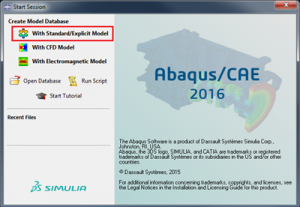
1) Launch Abaqus/CAE

2) Select the Model Database to Build (Typically Standard/Explicit)
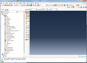
3) Select the Create Part icon in the CAE window
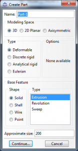
4) In the pop up box, specify the name of the part if required and the type of part. The Approximate Size is the size of the sketcher grid.
5) The Abaqus sketcher allows the user to pick geometry based tools on the left and sketch in the main window as per any CAD utility.
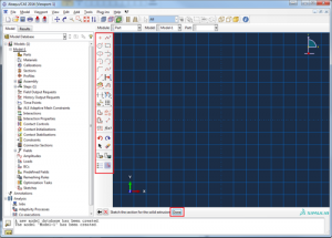
6) Upon creating geometry, additional inputs can be added at the bottom of the sketcher window.
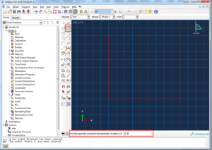
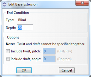
7) Once the geometry has been created, simply press the middle mouse button to confirm. Exit sketcher by pressing DONE or the middle mouse button again and select the options in the next window as required (In this example, this is an extrusion thus the depth of the extrusion is determined).
8) The Part is now created in the tree on the far left with all its features and the solid is now visible in the main design window.
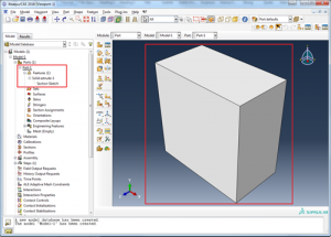
9) As you create more parts/features of a part to the model, these will all be added to the tree.

Want to Know More? Discover more about Abaqus/CAE and the SIMULIA Portfolio.


