CATIA V5: Save Time with 2D Advanced Meshing
CATIA V5 allows the user to perform Finite Element Analysis (FEA) using Generative Structural Analysis (GSA). This workbench is useful for analysis with 3D geometry, and in some cases (sheet metal, constant thickness parts, axisymmetric products, etc…) 2D can be used with the advanced meshing tool workbench.
This example is based on a simple sheet metal part with 2mm thickness.
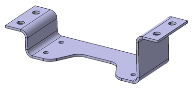
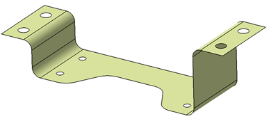
Based on this 3D part, a mid plane surface has been created with extract (Insert > Operation > Extract ![]() ) and offset (Insert > Surfaces > Offset
) and offset (Insert > Surfaces > Offset ![]() ) tool in the Generative Shape Design workbench.
) tool in the Generative Shape Design workbench.
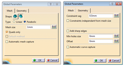
Now we can launch the Advance Meshing Tools workbench, select the analysis type (in this example it is a static analysis) and press OK. Select Advance Surface Mesher (![]() ) in the surface mesher toolset icons, click on the surface(s) and fill mesh size and sag. Be aware of the min hole size, this option would supress any hole(s) below the diameter entered in the window, leaving “0mm” will keep every holes features.
) in the surface mesher toolset icons, click on the surface(s) and fill mesh size and sag. Be aware of the min hole size, this option would supress any hole(s) below the diameter entered in the window, leaving “0mm” will keep every holes features.
An example 2D shape can be seen below. As you can see, you are now in the meshing editor workbench, where you can refine, transform or change element type.
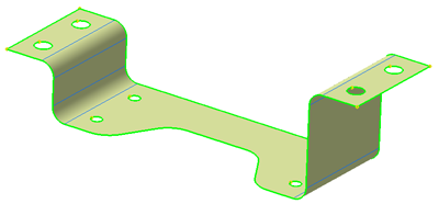
In this example we will just mesh the part (![]() ). A window will open with all the mesh info, number of nodes, elements, etc… you can now exit this workbench
). A window will open with all the mesh info, number of nodes, elements, etc… you can now exit this workbench ![]() :
:

Now the part is ready for the Generative Structural Analysis workbench. If your mesh does not appear, right click in the tree on Node and element > Mesh visualisation. Now as a usual 3D part, apply material, boundary conditions and loads. Unlike with the 3D part, you must apply a 2D properties (![]() ) to your part.
) to your part.
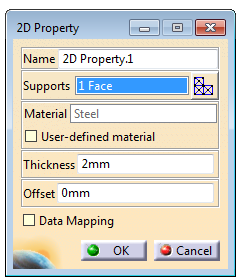
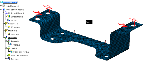
When your model is ready for analysis, your construction tree and model will look populated like the example below. You can then click on compute icon (![]() ):
):
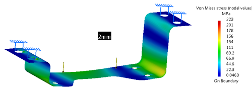
Next you can extract the relevant values from your analysis, for example maximum stress and displacement.
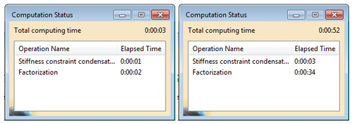
Now let’s compare 2D vs 3D in terms of computation time with the same element size, sag, loads and boundary conditions.

